

| LandingLens | LandingLens on Snowflake |
|---|---|
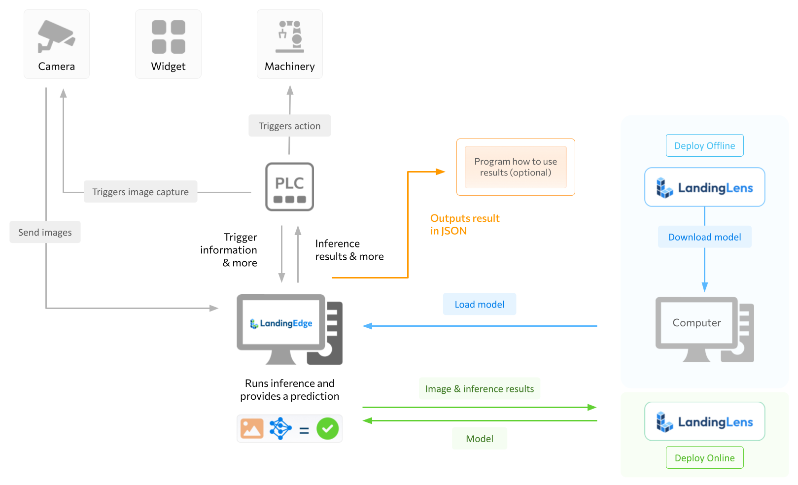
If using an industrial camera, you can configure a PLC to trigger image capture. To learn how to set up industrial cameras in LandingEdge, go to GenICam and GigE Vision Cameras.
Supported Controllers
LandingEdge is compatible with the following PLCs:- Rockwell CompactLogix controllers
- Rockwell ControlLogix controllers
- Controllers that use the Open Platform Communications Unified Architecture (OPC UA) protocol
Set Up Inspection Points for PLCs
You can set up multiple configurations for each Inspection Point.
- Create an Inspection Point.
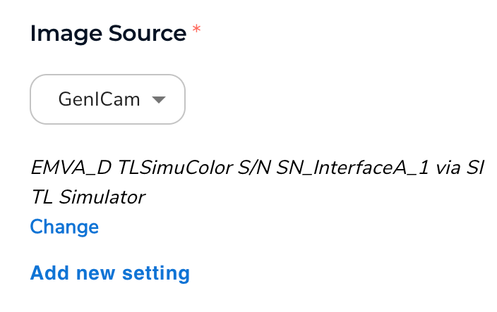
- Select your Image Source.If you want the PLC to trigger the inspection start and you are capturing images with a connected industrial camera, select GigE Vision Camera or GenICam and then select your camera.
- Select your Inspection Start method.If using an industrial camera, select PLC. Make sure you configure your PLC to start inspections. This will vary based on your PLC device.

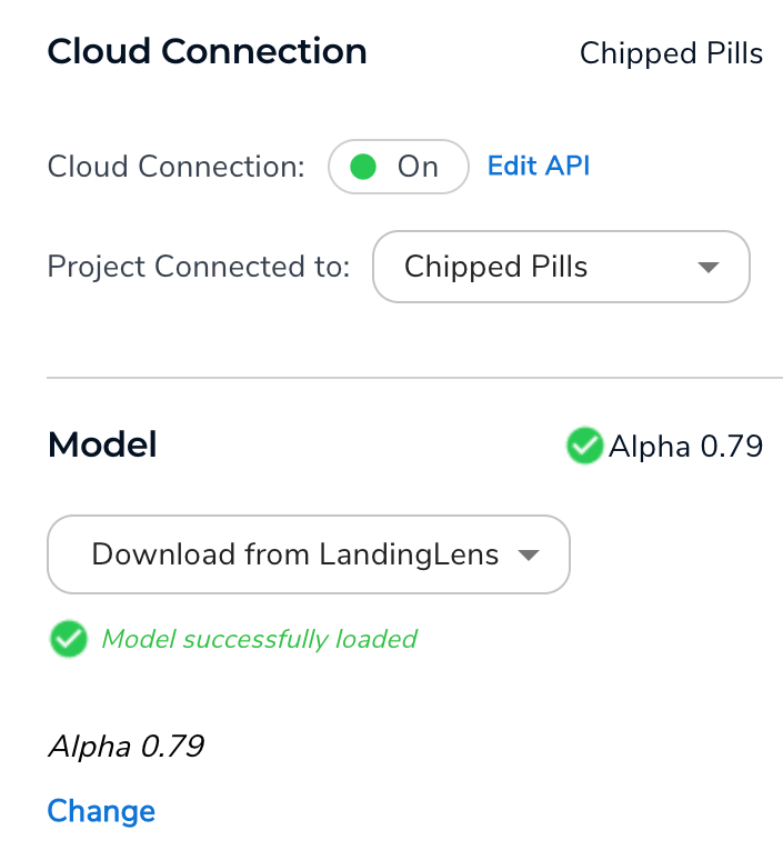
- Set up the Cloud Connection and Modelsettings.
- Complete the following steps in the Communication section.
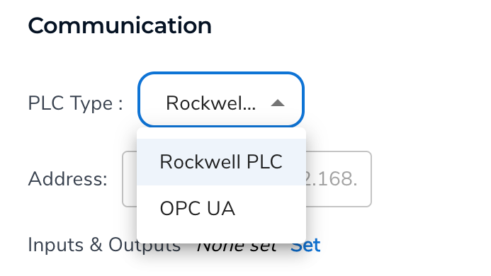
- Select your PLC Type.
- Enter the IP address of the controller in the Address field.
- For Rockwell controllers, use this format: [IP Address]/[Slot Number].Example: 192.168.1.5/0. (If there’s no slot number, omit it.)
- For OPC UA controllers, use this format: opc.tcp://[IP Address]:4840.Example: opc.tcp://192.168.1.10:4840.
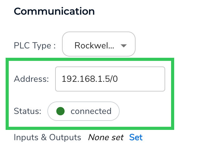
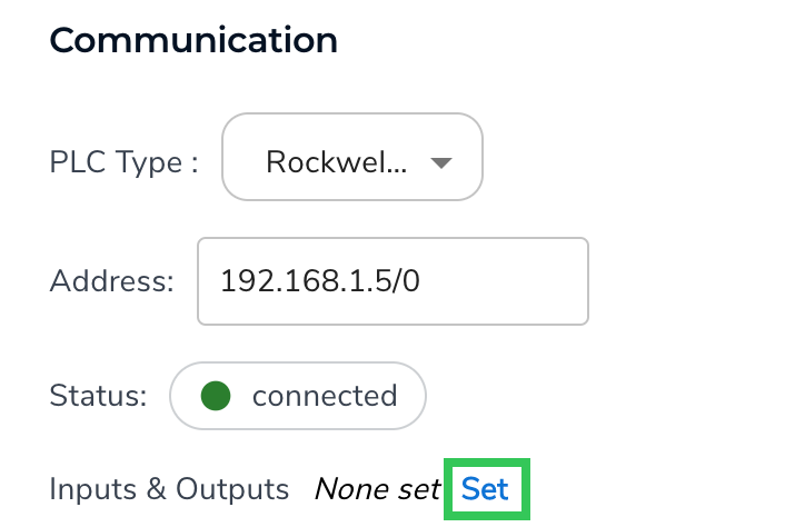
- Click Set to set up the Inputs and Outputs, which are the data points that LandingEdge and the PLC can share with each other.
- Click Add New Signal.
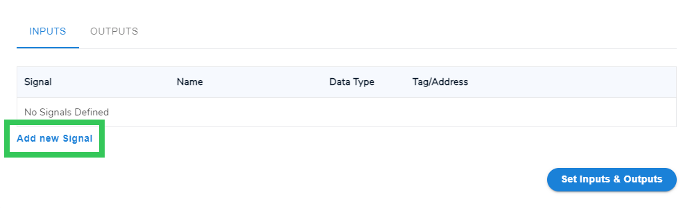
- Select an option from the Signal drop-down menu. For detailed information about the options, go to Inputs and Outputs.
- If you selected Custom, enter the Name and Data Type.If you selected an existing signal type, these fields auto-populate and can’t be changed.
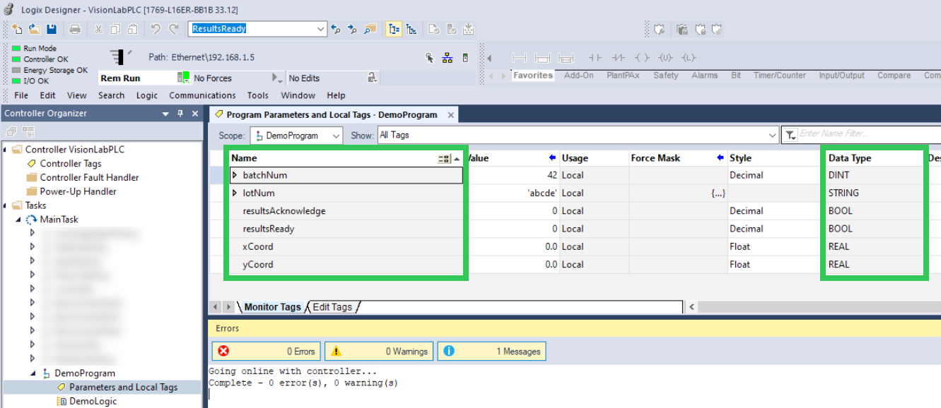
- Enter the PLC Tag or Tag Address in the Tag/Address field for that data point. This field isn’t case-sensitive. For information about how to program your PLC, refer to the device manufacturer’s documentation.For example, the images below show the signals in the PLC application and the matching signals in LandingEdge:

- After you’ve set up all the signals, click Set Inputs & Outputs.
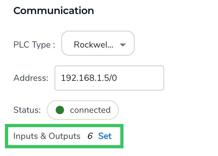
- Confirm that the Communication panel shows the number of signals you’ve set up.
- (Optional) Set up Image Saving settings.
- (Optional) Set up Other Settings settings.
- (Optional) Set up Custom Processing.
Inputs
Use the Inputs settings to configure the signals that the PLC sends to LandingEdge. The following table describes the configurable inputs.Refer here to understand the signals emitted by LandingEdge and the PLC:
• True/High: Indicates that the value is on.
• False/Low: Indicates that the value is off.
• True/High: Indicates that the value is on.
• False/Low: Indicates that the value is off.
Outputs
Use the Outputs settings to configure the signals that LandingEdge sends to the PLC. The following table describes the configurable outputs.Refer here to understand the signals emitted by LandingEdge and the PLC:
• True/High: Indicates that the value is on.
• False/Low: Indicates that the value is off.
• True/High: Indicates that the value is on.
• False/Low: Indicates that the value is off.
Test Inputs and Outputs
To test if a signal can be sent between LandingEdge and the PLC, click Test. If the signal works, Success displays. If not, Fail displays. If the test fails, check if the Name, Data Type, and Tag/Address in LandingEdge match the information in the PLC application. For example, the Custom “lot” signal in the image below failed because its address was incomplete.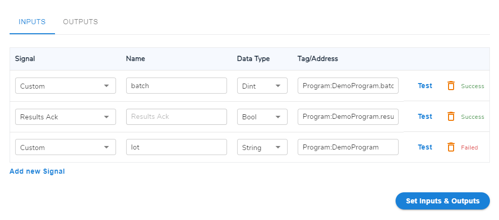
Example Setup of LandingEdge and a PLC
The following example workflow shows how setting up the Inputs and Outputs enable LandingEdge and the PLC to work together. The example assumes that these Inputs and Outputs are set up:Example Workflow
- LandingEdge indicates that it is Online.
- LandingEdge is ready and asserts Trigger Ready (True).
- The PLC asserts Trigger (True) based on the set configurations. LandingEdge receives this signal and recognizes it is time to take an image.
- LandingEdge changes Trigger Ready to False. The PLC receives this signal and recognizes that LandingEdge acknowledged the Trigger.
- LandingEdge asserts Busy (True) to indicate that it cannot be triggered again. The PLC can monitor this signal.
- After LandingEdge has received and processed an image, Result OK is set to True and Result NG is set to False.
- If using a Classification model, Classification is set to the predicted Class ID.
- If an error occurs, Error is set to True.
- After the Results are set, LandingEdge asserts Results Ready (True) to indicate that results are available for the PLC to read.
- The PLC recognizes that Results Ready or Error is set to True. It reads the appropriate values—like Results OK , Results NG, and Classification—to determine the final prediction from the model.
- After the PLC reads the results, it asserts Results Ack. LandingEdge receives this signal and recognizes that the PLC has read the results and the cycle is complete.
- LandingEdge resets the result signals and is ready to initiate the cycle again (starting from step 2).
Sample Script: Read Inputs and Write Outputs
You can add Results Processing scripts to any LandingEdge inspection point, including inspections with PLCs. When running inference with a PLC, you can use theReadInput and WriteOutput methods to customize processing based on custom signals defined in the Inputs and Outputs.
The scripts in this section show examples of how you can use these methods:
ReadInput: Save inferenced images to directories and filenames based on custom signals defined in the Inputs and Outputs.WriteOutput: Send the X and Y coordinates of bounding boxes of predicted objects to the PLC (applicable when using an Object Detection model).
lot: This is the lot number for a set of products, and is defined in the PLC.batch: This is the batch number for a set of products, and is defined in the PLC.x: This is the x coordinate of the bounding box for a predicted object of interest.y: This is the y coordinate of the bounding box for a predicted object of interest.
Results Processing Considerations
If you add a Results Processing script that pulls data from the PLC application (usingReadInput), LandingEdge will use the values the PLC application sent the last time that you acquired an image. If you change a value in the PLC application, you must capture another image to send the updated value to LandingEdge.
For example, let’s say you create a lot tag in the PLC application and set its value to 40. You then capture an image. At this point, the lot value in LandingEdge is 40. Let’s say that you now change the lot value in the PLC application to 50. If you run the Results Processing script in LandingEdge again without capturing an image, the value will still be 40. Once you capture another image, the value will change to 50.